Delay Line Reverberation
All discoveries, and even mistakes (especially mistakes) can be new points of departure for sound research: the absence of aesthetic objectivity leaves the door open to all types of sound. Nothing is to be discarded in past works.
Reverberation is a highly complex phenomenon that cannot be modelled in real time with today's equipment, and even less so with the technology available at the time of the first experimentations on the matter (60s-70s). Researchers therefore decided to limit themselves to a perceptive simulation of reverberation, working with an economy of means.
Table of Contents
- Time and Frequency Density
- Comb Filter
- Allpass Filter
- Schroeder Topology
- High Frequency Absorption
- Early Reflections
- Moorer Topology
- Modulation of Delay Lines
- Griesinger Topologie
- Allpass Ring
- Feedback Delay Network
- Modern Evolution
- Bibliography
Time and frequency density
The two crucial points in the design of a reverberation are :- Frequency density Df, defined by the number of modes per Hz
- Time Density Dt, defined by the number of echoes per second
- Df = 0.15 modes/Hz
- Dt = 1000 echos/seconds
Df being proportional to the reverberation time, 0.15 is the value for a 1 second
RT60
Reverberation Time 60dB : Time it takes for the reverb to lose 60 dB.
.
Dt is proportional to the sample rate, which was very low at the time,
it would be around 10k echos/s at
44.1 kHz.
From a perceptive point of view, too low a density will give a sensation of flutter (characteristic of small
rooms with parallel walls).
We're looking for the flattest possible frequency response, especially in the reverberation tail, which
researchers consider to be exponentially decreasing white noise.
Comb filter
Early reverberation simulations used an analog delay line (magnetic tape) to generate an echo. The output of
this echo could then be fed back to the input to generate successive, exponentially decreasing echoes.
This naïve method is fraught with problems, one of which led to one of the first papers on algorithmic
reverberation design. Indeed, M. R. Schroeder noticed that for short delays, approaching a reverberation
effect, the timbre of the source was strongly altered.
Summing a signal with its delayed version, as one does with a delay line in a feedback loop, gives a
comb filtering effect.

The transfer function of a comb filter is as follow
H(ω) =
|H(ω)| =

This filter, with its characteristic comb-shaped frequency response, produces a sound perceived as “metallic”. In order to increase time and frequency density, we need to use several delay units, of which there are two possibilities
- Paralleling, which multiplies Dt, but requires a very large number of units to achieve the suggested constraints (impossible with the technical means of the time)
- Serial connection, which exponentiates Dt, but greatly deteriorates the signal since the distortions of all the filters are superimposed. It is possible to limit the number of filters by reducing delay times, at the cost of a deterioration in timbre.
All-pass filter
Schroeder sought to design a new reverberation unit that would meet 6 constraints:
- Frequency response must be flat
- Reverberator modes must cover the entire audio spectrum
- The decay times of the individual modes should be close or equal, so that the different frequency components decay at the same rate.
- The transient response must be dense enough not to generate audible echoes.
- Reverberation should not suggest temporal periodicity
- Reverberation should not imply amplitude-frequency periodicity (as does the comb filter).
He then proposes a filter to validate points 1, 3 and 6. By adding the delayed signal with a gain inverse to the feedback gain, we effectively obtain a filter with a flat frequency response: the all-pass filter.

T(z) =
H(z) = e-iωτ
|H(z)| = 1
To validate the remaining points, it is once again necessary to use several units of this delay. Thanks to the properties of this new filter, we can now use them in series (and thus exponentiate the number of echoes), and thus achieve the recommended density values. These series of scatterers will form the basis of subsequent algorithms.
Schroeder topology
This results in a much more convincing reverberation tail, and makes it possible to add practical tools for
sound engineers: pre-delay and Dry/Wet mix (ratio of direct sound to reverberated sound, often in
percentages).
For pre-delay, simply add a delay line before reaching the reverberation. For Dry/Wet, you need
to be careful not to violate the principles established with the all-pass filter, by adding the necessary
gains to avoid falling back into comb filtering.
In many cases, the human ear can't tell the difference between a flat response and a sufficiently dense,
irregular response. In reality, room reverberation has an average fluctuation of 10dB and around 15 modes
per 100 Hz (0.15 modes/Hz).
Schroeder therefore uses 4 comb filters in parallel, generating 4 modes/Herz, but
only a hundred or so echoes per seconds.
He thus add 2 all-pass filters in series to get closer to the target of 1000
echos/seconds.

This topology makes it possible to simulate a wider variety of rooms and better tailor the reverberation tail to our needs.
High Frequency absorption
The path of sound through the air attenuates high frequencies, and this effect is far from negligible.
Moorer
gives the example of the Boston Symphony Hall:
A 1.7s reverberation implies 600m of distance traveled, which would mean (for 40% humidity), that a 4kHz
signal
would be attenuated by 60dB more than a 1kHz signal, which shows the importance of this parameter in the
reverberation tail.
In order to simulate the attenuation caused by the air, we can add a high-cut filter to the feedback
loop. It's
important to consider its stability given its context, so we prefer to use a finite impulse response filter
to
limit the risks. This type of filter is sufficient to simulate the desired effect.
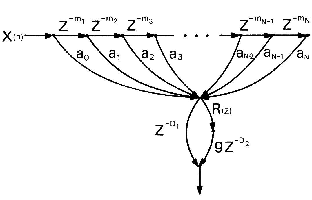
Early reflections
Early reflections remain one of the main areas for improvement. Unlike the reverberation tail, whose statistical description is largely defined by the volume of the room, early reflections are a series of discrete echoes, strongly dependent on the source/listener position. These first 80 milliseconds contain the information that enables our perception to characterize the acoustic space represented by the reverberation. But an exact simulation of this phenomenon can quickly become very computationally intensive, and therefore unthinkable for real time (at least at the time). One proposal is to split the reverberation into two, with an FIR filter for the first reflections, made up of a series of delays, followed by reverberators based on the schematics seen previously. To link these two systems, Moorer adds a reverberator to diffuse these first reflections, with a delay ideally equal to the last delay in the series, so that it starts at the end of the first reflections. This sequence of delays can be modeled on analyses of a real room for greater realism. Moorer recommends a minimum section of 7 delays.
Moorer topology
Moorer refined Schoeder's topology by adding early reflections and treble absorption, as well as refining the parameters already present. He gives the following guidelines for reproducing his work:
- The recursive part should consist of 6 parallel comb filters, each containing a first-order low-pass filter in the loop.
- Delays should be linearly distributed with a ratio of 1:1.5, the shortest delay being around 50 milliseconds.
- The outputs of the six comb filters should be summed into an all-pass filter network with a gain of 0.7 and a delay of about 6 milliseconds.
- Delay times in samples should be as close to prime numbers as possible, to avoid multiple delays looping on the same samples, creating audible peaks. (For high feedback values, sensitivity to exact size becomes negligible).
Modulation of delay lines
To break the repetition patterns in reverberation tanks, the delay times of the delay lines need to change over time. To achieve a transparent effect, it is necessary to generate a slow, subtle movement, which requires the calculation of interstitial samples. As the data vectors are discrete, what do we do when the modulation asks for sample 1.5? This technique requires an interpolation algorithm. This algorithm needs to be as efficient as possible in terms of computing resources, as it will be multiplied by the number of delay lines, and is only a secondary system in the operation of the reverberation.
Linear interpolation:
Linear interpolation is the simplest form of interpolation and linearly calculates the average between two
samples.
O[n] the output sample, Buf a vector of audio samples,
i.frac the index (decimal part .frac) of the sample to
be accessed.
In practice, we have a low-pass filter with a variable coefficient
Linear interpolation therefore has several disadvantages:
- Amplitude distortion: low-pass filtering process with a dynamic zero at the Nyquist-Shannon frequency.
- Amplitude modulation: modification of filter coefficients introduces audible flutter.
- Phase distortion: because each filter has non-constant delays
- aliasing: an upward pitch corresponds to a reduction in sampling frequency.
We can try to limit amplitude distortion by using all-pass interpolation
All-pass interpolation :
A recursion weighted by an opposite gain is added. However, this technique has one major drawback: the exact frac value is followed less precisely. This results in greater distortion, limiting this polyphasic filter to micro-tone changes (+/- 1 semitone). We can limit this distortion in certain frequency bands by warping the parameter values, replacing 1 - frac by (1 - frac) / (1 + frac). To generate larger pitch changes while maintaining correct signal quality, the simplest solution is to return to linear interpolation, having first performed a significant amount of up-sampling on the signal.
Modulation Signals
Delay line Modulation produce a pitch modulation artifact, in the way of a tape being slowed down or sped up. Ideally, modulation signals must be decorelated to avoid a global pitch movement, giving a "seasick" sensation in the reverberation tail. Altought strong modulation can be welcome in some effect-type reverb. In some early reverberation, numeric signal where used for modulation, but their low resolution (8 bit) can create audible artifacts. It may be considered as a part of the character of the unit, but it shows that modulation signals are an integral part of the overall sound of the reverberation and shouldn't be overlooked.
Griesinger Topology
This topology, which can be found in Jon Dattorro's papers, is a Lexicon algorithm used to reproduce the
impulse response of a reverberation plate.
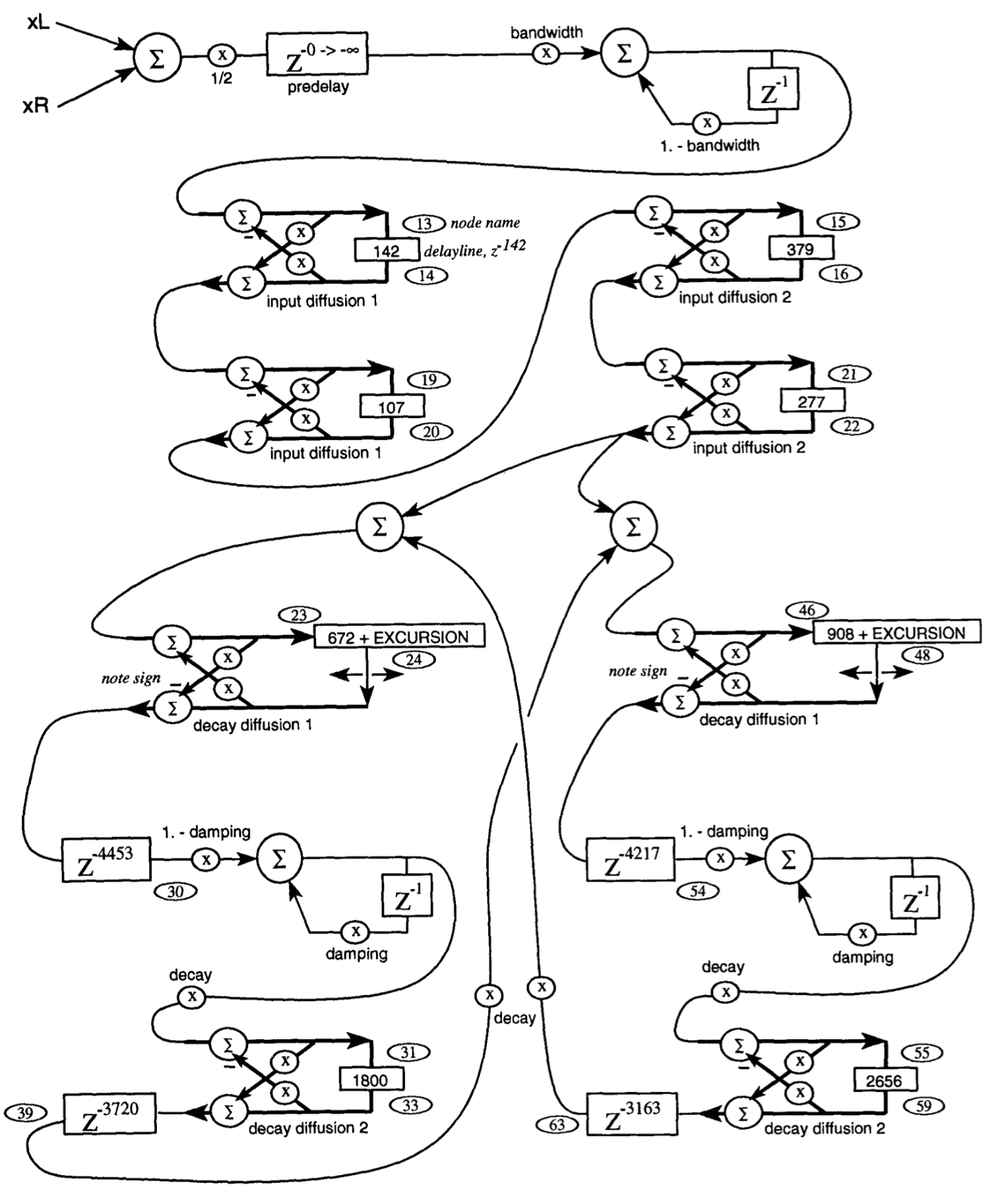
This mesh is composed of the elements seen above,
- Delays : Z-n blocks.
- All-pass filters : with the two sums and a feedforward / feedback.
- low-pass filters : little feedback loop with one sample delay and two coefficient (effectively doing an averaging between the actual and the previous sample)
The signal is first diffused through the 4 all-pass filters at the top (in series), then sent to the reverberation tanks, which recirculate the signal and significantly increase the total reverberation time. We can see that reverberation tanks have much larger delay lines than the first all-pass filters. The reservoirs also contain filters to simulate treble absorption. The output of this reverberation is a weighted sum of all the sampling points indicated by numbers along the path.
Allpass Ring
There's not much information available on allpass rings, although it seems to be quite common in commercial reverbs. You can find traces of it on a forum about signal processing. This topology consists of a long series of looped all-pass filters with several input and output points.
Feedback Delay Network
To simplify the study of recursion networks, Jot proposes to define a parallelization of filters whose
recursion gains would be managed by a matrix distributing the signals over several filters.

In this one-output, one-input diagram, the coefficient matrix can be seen at top right. On each recursion path there is a delay line and a high-cut filter for high-frequency absorption. Jot draws the following conclusions from his observations :
- system stability is guaranteed in the case where the feedback matrix is the product of a unitary matrix and a diagonal matrix whose elements have a magnitude less than 1.
- Choosing a unitary feedback matrix forces all the system's poles to lie on the unit circle, so the system has only non-decreasing modes.
- If the matrix is diagonal, we return to the case of parallel comb filters.
Modern Evolution
Engineers continue to develop new techniques: Sean Costello, the person behind Valhalla DSP, uses a system that borrows from both the all-pass series and FDN, making FDN's recursion paths more complex by replacing the usual delay unit with 3 all-pass filters.
Bibliography
- DATTORRO, Jon. « Part 1: Reverberator and Other Filters ». Journal Of The Audio Engineering Society 45, no 9 (septembre 1997): 660-84
- DATTORRO, Jon. « Part 2: Delay-Line Modulation and Chorus ». Journal Of The Audio Engineering Society 45, no 10 (octobre 1997): 764-88
- MOORER, James A. « About This Reverberation Business ». Computer Music Journal 3, no 2 (juin 1979): 13. https://doi.org/10.2307/3680280.
- SCHLECHT, Sebastian J. « FDNTB: The Feedback Delay Network Toolbox », Proceedings of the 23rd International Conference on Digital Audio Effects (DAFx2020), Vienna, Austria, September 2020-21
- SCHLECHT, Sebastian J., et Emanuel A. P. Habets. « On Lossless Feedback Delay Networks ». IEEE Transactions on Signal Processing 65, no 6 (15 mars 2017): 1554-64. https://doi.org/10.1109/TSP.2016.2637323.
- SCHROEDER, R. « Natural Sounding Artificial Reverberation ». Journal Of The Audio Engineering Society 10, no 3 (juillet 1962): 219-23
- SCHROEDER, R. « ”Colorless” Artificial Reverberation ». Journal Of The Audio Engineering Society 9, no 3 (juillet 1961): 192-7
- DE SENA, E. et al., Scattering Delay Network: an Interactive Reverberator for Computer Games. Présenté à l’AES 41st International Conference à Londres, Royaume-Uni, les 2-4 février 2011.
Additional Ressource :
- Artificial reverberation chapter of "Physical Audio Signal Processing"
- Pure data exemple of some reverbs (sadly I have lost the source...)